|
[this
is a post from the cannabis.com message archives.
It was posted by a resident poster there by the name of SCW.]
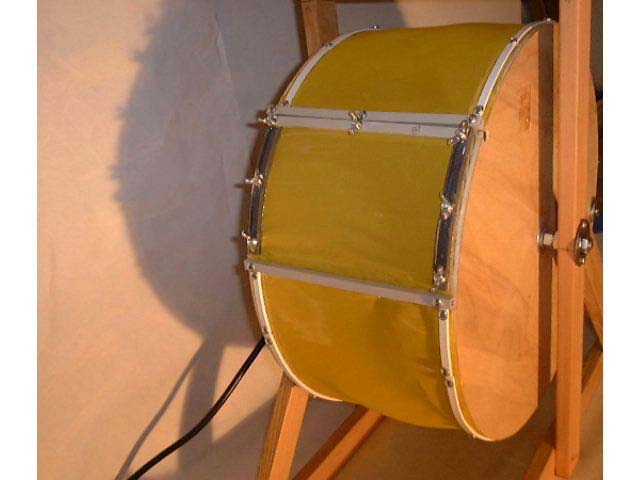
1. General construction The machine is basically like a squirrel cage, with the pot being the squirrel. Two circular plywood sides are aligned on a shaft, with silk-screen netting between. The cage is rotated with a motor, and the glands fall through the screen to be collected on a base, like a piece of glass, or perhaps foil. The device itself can be made with hardware store parts, with one exception; you need a motor. It should turn no faster than about 10-15 RPM, and needs to have good torque to handle the out-of-balance condition of the device when loaded. A rotisserie motor is perfect. I bought one from a cooking supply store for $43, the most expensive item on the device. Some Home Base type stores may have units designed for outdoor use. If you're lucky it will come with a metal bracket to hang the motor. 2. The shaft and cage The sides of the cage can be just about anything. I choose 3/4" plywood for two reasons; circular pieces were available already cut down at Home Base in that width, and the wide edge gives you plenty of area to mount the screen. The sides need to be held parallel on a shaft at some distance. I choose 6 1/2" pretty much arbitrarily, except that the total width of the screen, including the width of the plywood sides, was 8", and that made for even strips I could cut from the silk screen frame I was working with. The diameter of the wheel is also variable. I choose 16", as a larger wheel seemed to require a more substantial structure to hold it together. But the device turns very slowly, so it does not need to be very strong and the tolerances do not need to be tight. The choice
of shaft was easy; a 7/16" threaded rod. The threads give you
a way to mount the plywood sides on the shaft with nuts. I also
used a short piece of steel tubing on the shaft between the sides
to hold the sides in place, but plastic pipe should be fine. Why
7/16"? Because all 3. The frame and bearings The easiest frame to hold the wheel would be two parallel pieces of plywood, stiffened with cross pieces. I choose to be a little more elegant, so I used 1 x 2 hemlock pieces to build an open frame. The threaded shaft needs to be located in the frame with a bearing surface. If it was a smooth piece of steel, you could go with a bronze sleeve, since the device turns so slow. But a threaded shaft would cut up the bronze in short order, so a ball bearing unit is required. I found cheap 7/16" bearings at Home Base in the nuts and bolts area in a speciality cabinet.
I gather
that the best screen for skuffing is 100 mesh steel, but I couldn't
locate that. So I settled for silk screen material that I cut out
of frames I purchased at a printing supply shop. Only one large
frame was needed, and it was on sale for about $25. I ended up trying
different mesh screens and went over budget, but if I had it to
do again, I would have just bought a 110 mesh standard How to hold the screen on the wheel? I thought of several ways, including glue, like Liquid Nails. I ended up settling on plastic strips drilled and screwed to the plywood wheel edge with small pan head screws. I bought the styrene strips at a local hobby shop, but later found cheapo plastic moulding at Home Base with the exact right width. Live and learn [in making additional drop-in wheels, I still used the hobby shop styrene strips - ed]. Now,
how do you get the pot in and out of the wheel? Two ways. First,
you could take a jig saw and cut a hole in one of the plywood sides.
I planned on doing so,until I thought of how to hang the door and
how to seal it, and what a pain in the butt it would be to get the
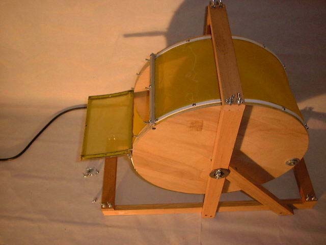
pot out (turn the whole So, I determined to find a better way, and settled on a flap in the screen. The screen is screwed down around the wheel except for a 4-5" section. I mounted nut studs in the wheel, and drilled holes through a section of the plastic strip to fit over the studs. A cross piece of hobby hardwood fits across the end to provide stiffness. Wingnuts hold the flap down on the wheel. To open the unit you spin the wingnuts, lift the flap off the studs, hinged just with the screen material, and just let the flap flop down. It's easy to unload, you just turn the wheel and the pot flows right out the opening. It's not real sturdy, but it doesn't have to be.
Step
one is to mount the circular plywood sides on the 7/16" threaded
shaft. I cut a piece of steel tube 6 1/2" less the width of
two large washers, and drilled a hole in the center of each plywood
wheel. I put one wheel on the shaft, ran a washer up against it,
dropped on the steel tube and another washer, and then completed
the sandwich with the other plywood side. To hold the unit together
I ran up washers and lock rings on both sides and bolted it together
with 7/16" standard nuts. I used two per side to provide some
clearance. That made it easy to bolt the shaft up tight I didn't worry about the length of the threaded shaft at this point, I just left plenty of length hanging out both sides. 6. Building the frame I cut two lengths of 1 x 2 24" long (the width of the mirror I use as a collection base), which is plenty of length for stability. I cut two more 1 x 2 pieces equal to the diameter of the wheel plus three inches on the bottom and one on top for clearance. I glued and screwed the two pieces together in a T shape and allowed the glue to dry. To add stability, I created a stiff triangle by adding a 1 x 2 diagonal brace, which runs from the pivot point to the base. It's easy to cut the brace if you use the T section as a template, first marking a line where it crosses the upright piece, cutting it, putting it back in place and marking where the base piece crosses it. I screwed and glued these into place, with Liquid Nails and #6 self-drilling screws, after drilling a pilot hole in the 1 x 2 with a combination bit that also chamfers out a depression for the screw head (a couple of bucks at the hardware store). Otherwise you will split the wood. The next
step is to mount the bearing at the pivot point. Home Base must
have been missing some pieces, as the bearings were just smooth
steel with no way to mount them to anything. Oh well, no biggie,
I drilled out a hole in the 1 x 2 vertical pieces with a 1 1/8"
hole bit, just to the depth of the bearing body. I then drilled
a 3/4" hole from the back to provide clearance for the nuts
bolted to the shaft. To hold the bearing into place, I could have
glued it, and that probably would have been fine. But instead I
found a big flat steel washer the right size, and drilled a couple
of holes in the edge, placing the washer over the bearing and fastening
the washer to the 1 x 2 upright with a
The next
step was to partially assemble the unit. I added a 7/16" jam
nut on each side of the wheel assembly and placed the frame sides
on the shaft, bolting up another jam nut on either side to hold
it all together. I gave it a spin to make sure nothing was hanging
up. I then arranged the frame on a level surface and squared everything
up. When I was happy with the arrangement, I measured across the
unit for support brackets. I used three cross pieces, one at each
end of the base and one right across the top of the uprights. Diagonal
bracing was considered, but it didn't appear to be I wanted to be able to take the unit apart for storage, so instead of gluing and screwing the support brackets to the frame, I mounted nut studs in the frame and drilled holes in the brackets, which are held to the studs with wing nuts [the main advantage of the wingnuts is the ability to make up wheels with different mesh screens and drop them right in the basic frame - ed]. Once
the frame was complete, I marked the shaft on one side to cut it
off just past the outside bearing jam nut. The other side will be
driven by the rotisserie motor, and here's where some fancy engineering
might be required. I was lucky, and my motor came with a steel bracket
that the motor I took the unit apart and cut the shaft ends with a dremel tool (using the large fibre cutoff wheels).
The end of the shaft on the motor end needs to have a 5/16" square section filed or cut out of the 7/16" round steel. I used a dremel tool with the small heavy duty ceramic cutoff disks, working slowly and carefully, and test measuring often. It was actually very easy to do, as the threaded shaft was soft steel, and you could easily do it with a file. After
I was sure the end was right, I re-assembled the unit. To mount
the motor, I held it to the end of the shaft and marked where the
bracket needed to be, adding a vertical 1 x 2 support at that point.
I doubled the thickness by adding another 1 x 2 glued to the support,
and added a horizontal To be able to take the unit apart, I added three more nut studs on the motor support 1 x 2 and drilled three matching holes in the steel support, which I mounted with wing nuts. Next I plugged it in and turned it on; success! It spun very nicely.
At this
point I started to mount the screen. The screen is not long enough
to go all the way around the wheel, so you have to glue the ends
together (Liquid Nails). I wanted to support the screen at those
points, and at the opening, so I added small wood cross pieces inside
the wheel. They also I started by adding one of the cross pieces and screwed the screen to it and the edges of the wheel with a plastic piece covering the screen to hold it down. I then draped the screen over the wheel and fastened it down with pre-drilled plastic strips using self-drilling pan head screws. Half way around where I ran into the glued seams, I added the other cross pieces, and screwed the screen down to that as well, with another plastic stiffener across as support to hold the screen down. Where
the screen completed the circle, I cut it off square. I then marked
the area where I wanted the flap opening, and added the last plastic
strips to the edge of the plywood right up to the opening. I then
added 7 nut studs, two on the edge of the wheel along the sides,
and three across For the
end I added a small piece of hobby hardwood. I filed slots in the
ends so that the plastic strips would fit under the wood cross piece,
and after making sure everything was aligned, I glued the plastic
and wood together while bolted to the wheel with the screen in place.
I used painter's I then removed the motor to allow the wheel to spin freely, and balanced it by screwing steel washers to the side as needed. That's it.
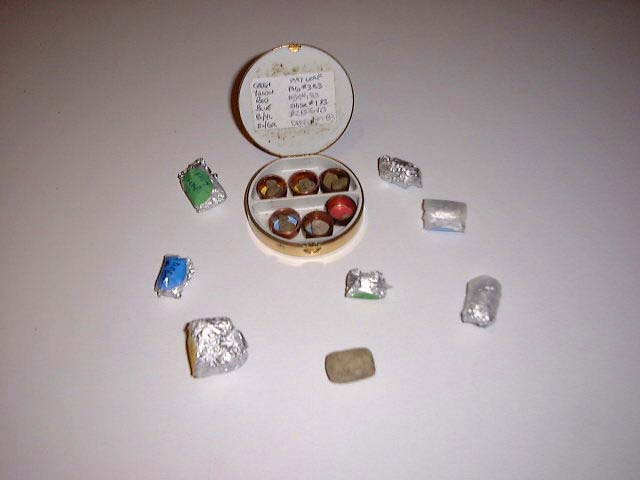
To open the unit, first you spin off the wingnuts holding the wooden cross piece at the end of the flap, then the next lower set of wingnuts and then the last set at the hinge end of the flap. The flap peels itself right off the wheel as the plastic strips straighten out. The flap just hangs off the wheel connected only by the screen fabric itself. Dump some pot inside, and then re-bolt the flap to the wheel the other way around, first with wing nuts near the hinge, then in the middle and finally across the wood end piece. You may have to bend the studs a bit to allow the wood piece to clear the ends depending on the thickness of the piece (there are about a thousand other types of material you could use, but this works). Turn on the motor and wait. It takes at least an hour, and given the relatively small diameter of the wheel, maybe more [that's not quite true, it depends very much on the mesh size and the type of hash you want - ed]. Again, rotisserie motors are perfect, as they are designed to operate for hours-long periods. You measure your progress by examining the deposits. You want stalked glands and gland heads, not hairs or mineral trichomes. I am told that it is easy to see when no more glands are coming through the screen, but I don't have enough hands-on experience to provide much guidance [I do now! Just ask - ed]. To empty the unit, just undo the flap and rotate the wheel until the pot plops out. That's all there is to it. Knock yourself out [literally - ed]. [Kudos to the great oldtimer1 for the basic design of the unit, and for the inspiration to build it. Good hash can be made by flat screening or in a blender, but for control of the output, nothing beats a rotating machine - ed]
|